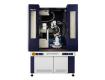
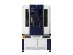
Sistema de medición de tensión residual por difracción de rayos X (DRX)
Laboratorio Rapid de análisis de micropuntos con métodos iso y de inclinación lateral
AutoMATE II
Residual stress may be created during the manufacturing process of a material, or it may accumulate in a structure over many years in operation. In either case, this stress can have a serious negative effect on a product's quality, durability and lifetime. Accurate detection of residual stress is an important element of the quality control process and helps predict the service lifetime of products.
In the past, if you wanted to make highly accurate residual stress measurements, you had to use an R&D diffractometer because of the accuracy of the goniometer. However this restricts the weight and size of the samples you can measure. On the other hand, dedicated laboratory and factory-floor residual stress analyzers suffer from reduced accuracy due to the nature of their mechanical designs, while, in their favor, they have the flexibility of measuring large and heavy parts.
With the AutoMATE II, you now have the best of both worlds. Large and heavy parts (30 kg with standard manual Z stage; 20 kg with optional automated XYZ stage) can be measured with high accuracy.
The X-ray source and detector arm are mounted on a highly accurate two-axis goniometer that can position them relative to the measurement site and perform scans with minimum steps of 0.1 microns when using the automated XYZ stage.
The most advanced new feature of the AutoMATE II lies in an innovative new X-ray detector. The detector used in the AutoMATE II is the D/teX Ultra1000, an electronic Si strip detector that has high dynamic range, high sensitivity, and good energy resolution, as well as not requiring any consumable gas.
Features
- Highly accurate goniometer allows for true micro-area residual stress measurement.
- Automatic mapping measurements with teaching function.
- Large and heavy samples are measured with high accuracy.
- An X-ray radiation enclosure with interlock system automatically locks the enclosure door when the X-ray shutter is open.
- The measurement position is adjusted by a CCD camera equipped with a microscope having a zoom function.
- The two-axis goniometer system allows for both iso-inclination
and side-inclination methods automatically without readjustment of the sample position.
X-ray generator | ||
Maximum power | 3 kW (Tube voltage 20 - 50 kV, Tube current 2 - 50 mA) | |
Stability | ±0.03 % (Power fluctuation within ±10%) | |
X-ray tube | Standard: Cr (Maximum load 2 kW), Effective focus size 1 × 10 mm2 (N.F.), Short type Option: Cu (2 kW), Co (1.8 kW), Fe (1.5 kW), V (0.3 kW) |
|
Goniometer | ||
2θ scanning range | 2θ = 98° to 168° (Central angle range of D/teX Ultra 1000 2θc = 108° to 158°) | |
ψ angle range | ψ = 0° to +60° (at maximum) | |
Oscillation range | ψp = ±1° to ±10° | |
Incident collimator |
Standard: φ150 μm, φ1 mm Option: φ30 μm, φ50 μm, φ100 μm, φ300 μm, φ500 μm, φ2 mm, φ4 mm | |
Distance | X-ray source - sample: 265 mm Sample - detector: 210 mm |
|
Sample stage | ||
Standard: Manual Z stage | Lab. jack (Model LJA-16223) Maximum sample space: 720 mm (W) × 560 mm (D) × 540 mm (H) Stage dimensions: 160 mm × 220 mm Maximum load: 30 kg |
|
Option: Auto XYZ stage | Maximum sample space: 720 mm (W) × 560 mm (D) × 335 mm (H) Stroke: X-Y axis = ±50 mm, Z axis = -5 mm to + 35 mm Stage dimensions: 150 mm × 150 mm Maximum load: 20 kg |
|
X-ray shutter |
Rotary shutter | |
Sample alignment system | CCD camera |
Magnification: ×22 to ×135 (Field of vision 6 mm to 1 mm) Focal distance: 90 mm |
Detector (D/teX Ultra 1000) | ||
Dimension |
One dimension (Semiconductor system) | |
Number of channels | 1024 ch | |
Maximum counting rate | 1 × 10⁶ cps/ch × 1024 ch (Total 1 Gcps/all) | |
2θ angle resolution | 0.02° (Strip width 75 μm/line) | |
Window area | 76.8 mm × 10 mm | |
Size, Weight | 135 mm (W) × 95 mm (D) × 100 mm (H), 1.4 kg | |
Kβ filter | Standard: V (Cr)Option: Ni (Cu), Fe (Co), Mn (Fe), Ti (V) |
Table II. Specifications of software
Software | Residual stress (Measurement) |
sin2ψ method Iso-inclination method, Side-inclination method ψ0-fixed method X-Y teaching function |
Residual stress (Data processing) |
Batch processing of multiple data Smoothing Background elimination LPA correction Kα1, Kα2 separation Peak search (FWHM center method, Parabolic approximation method, Center of gravity method, FW2/3M center method, FW2/5M center method) |
|
Retained austenite (Measurement) |
α-Fe(211): 2θ = 156.40° (Cr Kα), γ-Fe(220): 2θ = 128.83° (Cr Kα) X-Y teaching function |
|
Retained austenite (Data processing) |
Batch processing of multiple data Normalization factor of diffraction intensity: R = 0.36746 (or user setting value) |
Table III. Specifications of utilities
Cooling water system (TCA2KCN-D) |
Cooling system | Air-cooled water chiller |
Cooling capacity | 2 kW | |
Cooling temperature range | 15°C to 25°C | |
Computer | PC | Desktop personal computer |
OS | Windows® 7 Professional (32 bit) | |
Display | 19" TFT | |
Printer | Ink jet color printer | |
Computer rack | Vertical type |
Evaluation of the effects of shot-peening treatment on the surface of a spring by X-ray stress measurement

Mapping measurement of the weld bead on a SUS304 plate
On the weld bead, the residual stress is approximately equal to zero. Tensile stresses from 200 MPa to 300 MPa are observed in the heat-treated area in the base metal. In the sandblasted area, the mapping chart shows that the tensile stress has changed to the compressive stress of about -1000 MPa by the sandblast treatment. By using the CCD camera with a zoom function, the images of the sandblasted and non-sandblasted areas are recorded as shown in the pictures.![]() |
![]() |