X-ray diffraction can provide the orientation of a film with respect to its substrate. The technique involves collecting pole figures (below, left) which are stereographic representations of the grain orientations in three-dimensional space. Two-dimensional detectors can collect large sections of many diffraction cones simultaneously, which enables a complete range of grain orientations to be observed. Texture strength can be quantified using Orientation Distribution Function (ODF) software. At least three pole figures are required for ODF analysis, which may lead to undesirably long data collection times. In addition, many ODF programs have difficulty handling sharply textured materials, which is the case with many electronic thin films. Since most thin films reflect symmetrical fiber or near fiber texture, in which the orientation precesses uniformly and randomly about the substrate normal, the texture strength can be quantitatively represented from a single pole figure as a Fiber Texture Plot (FTP, below, right).
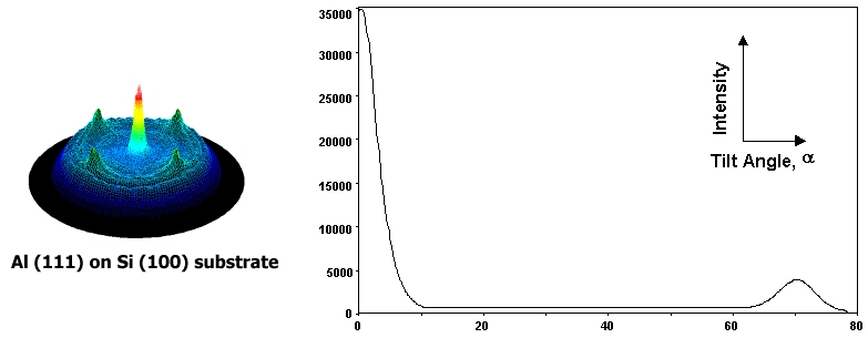
The FTP is essentially a slice integration from the center (α = 0°) to the outer edge (α = 90°) of the pole figure. An α = 0° represents reciprocal lattice planes oriented parallel to the substrate, while an α = 90° represents reciprocal lattice planes oriented perpendicular to the substrate (see Diagram 1). In reality, measurement of orientation perpendicular to the substrate requires X-ray diffraction in transmission rather than reflection, so most FTP representations extend from α = 0° to α = 85°. The example shows the Al (111) planes parallel to the Si (100) substrate. Since Al is cubic, the angle between the (111) plane and the other <111> family members is 70.5°, which is verified in the FTP by the second intensity peak. It is important to remember that the crystallographic system of the film dictates where intensities are expected to be observed in FTPs. The reciprocal and direct (real) space crystallographic directions are only coincident in cubic systems. For example, in Ti which has a hexagonal lattice, the (100) reciprocal lattice plane is perpendicular to the [210] direction, not to the [100] direction. The shape of the FTP curve provides a simple qualitative picture of the fiber or near fiber texture. The area under the FTP can be integrated to obtain a quantitative representation of the texture strength, from which pole spread and/or pole tilt can be quantified. With appropriate background correction of the measured raw data, the linear background under the FTP can be used to quantify the % random distribution of the grains. Texture quantification is reported as the volume fraction or half width, ω90, ω63, and ω50, where ω represents the half angle (in degrees) in which a specified fraction of the intensity (90%, 63%, 50%) is contained. For example, the half angle containing 50% of the (111) grain orientations is ω50. From this definition, the smaller the value for ω50, the narrower the (111) grain distribution (the smaller the pole spread) and the stronger the texture. For the FTP above, the reported ω values representing the pole spread and texture strength are ω90 = 3.2°, ω63 = 2.7°, and ω50 = 0.8°, with 4% randomness. The value τ represents the angle between the substrate normal and the normal to a given diffraction plane. It is sometimes called the "off-cut" or "mismatch" angle. Its value is not important for the determination of α, but is required to determine the relationship between the film and substrate orientations. Because the FTP is essentially a slice of a complete pole figure, some of the information available in a complete set of pole figures is absent. For example, if the pole is not completely symmetric about the perfect fiber normal, which can occur if the pole is tilted or spread in one direction, the slice selected may misrepresent the true texture. For this reason, it is often useful to create FTPs from both one slice (of about 10°) and from a full 360° pole figure integration. Otherwise, the more general ODF analysis is required.